Sentinel-2 MSI Synthetic Raw Data Generator
Overview
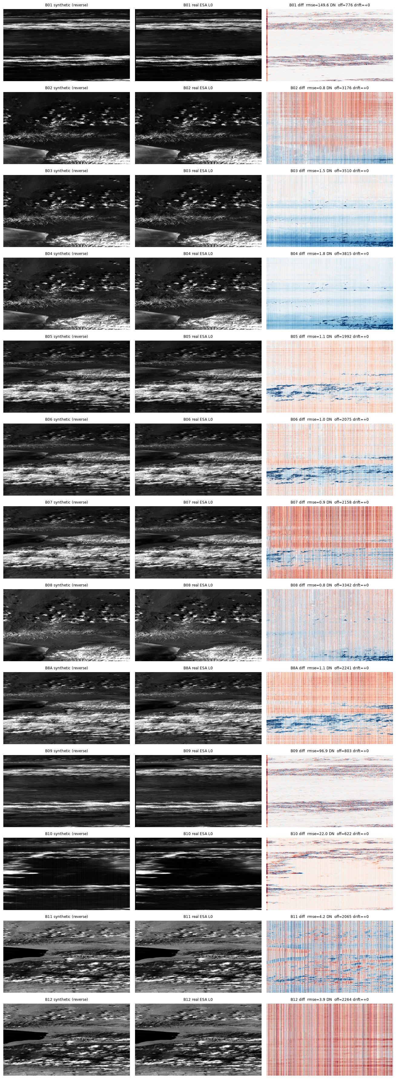
Runs S2B L1B backwards through the exact inverse of the operational L0→L1B radiometric chain to reconstruct the full EOPF product chain — L1A → L0plus (CCSDS-122 ISP) → Synthetic L0 (focal-plane DN img, 12 detectors × 13 bands). The Synthetic L0 is validated directly against the reference ESA L0 img, agreeing to ≤ ~4 DN on the ten 10 m + 20 m bands.
The inversion undoes every ON forward step — radiometric offset, relative-response/PRNU, dark, un-bin, SWIR re-arrangement, defective pixels, crosstalk, on-board equalization. MTF-deconvolution is OFF in the operational chain, so PSF re-blur and noise are not re-applied. Built from the public L1 ATBD — no external processor.
It also derives a calibration database (EOPF ADFs) consumed by the downstream msi-processor.
Architecture
flowchart LR
    IN[("S2B L1B<br/>EOPF product")]
    ADFsrc[("ADF sources<br/>GIPP - PSF - SRF")]
    subgraph GEN["s2_msi_raw_generator — reverse chain"]
        REV["reverse_l1b_to_l0"]
        L1A["write L1A"]
        C122["CCSDS-122 lossless"]
        PKT["ISP packetize → L0plus"]
        CAL["calibration.py"]
    end
    L0plus[("L0plus compressed ISPs")]
    L0[("Synthetic L0 decoded img")]
    REFL0[("reference ESA L0 img")]
    CALDB[("cal-DB EOPF ADFs")]
    VAL["validate: Synthetic L0 vs reference ESA L0 ≤ ~4 DN"]
    IN --> REV --> L1A --> C122 --> PKT
    PKT --> L0plus --> L0
    CAL --> CALDB
    L0 -.-> VAL
    REFL0 -.-> VAL
Key technical work
- Reverse radiometric chain (S1–S15) — inverts radiometric offset, binning, defective pixels, SWIR re-arrangement, relative response, crosstalk, dark, and on-board equalization per the operational ATBD.
- CCSDS-122 codec — lossless DWT 9/7-M + bit-plane coder; L0plus round-trip is bit-exact (
decode(L0plus) == L1A), lossless ratio 3.66×. - Calibration database derivation — derives D, g, A coefficients from diffuser + dark acquisitions; non-tautological round-trip with the consumer processor.
- S2 L1B E2E validation — 2024-04-08 S2B PPB Synthetic L0/L1B pair, detector d05, framing-aligned to ADF_PRDLO co-registration crop.
Results
Synthetic L1A vs reference ESA L0 img — detector d05:
| band | B02 | B03 | B04 | B05 | B06 | B07 | B08 | B8A | B11 | B12 |
|---|---|---|---|---|---|---|---|---|---|---|
| RMSE (DN) | 0.8 | 1.5 | 1.8 | 1.1 | 1.0 | 0.9 | 0.8 | 1.1 | 4.2 | 3.9 |
| resolution | 10 m | 10 m | 10 m | 20 m | 20 m | 20 m | 10 m | 20 m | 20 m | 20 m |
All ten 10 m + 20 m bands agree to ≤ ~4 DN. Native-60 m bands (B01/B09/B10) have higher RMSE because reverse un-bin is ×3 line replication — sub-pixel detail averaged away by forward binning is irrecoverable.
| Forward step | Reverse op | ADF / GIPP |
|---|---|---|
| radiometric offset | + RADIO_ADD_OFFSET (−100) |
R2PARA |
| binning (60 m) | ×3 un-bin (replication) | — |
| defective pixels | re-stamp NoData | R2DEPI |
| SWIR re-arrangement | re-introduce staggered readout | RSWIR |
| relative response | impress G⁻¹ | R2EQOG |
| crosstalk | add back | RCRCO |
| dark | + L0-domain dark × DSNU shape |
R2EQOG COEFF_D |
| on-board equalization | re-apply bilinear non-linearity | REOB2 |
Links
Documentation (GitHub Pages)
Project documentation
- Algorithm Theoretical Basis Document (ATBD)
- Software System Specification (SSS)
- Software Requirements Specification (SRS)
- Interface Requirements Document (IRD)
- Software Design Document
- Design Justification File (DJF)
- Interface control document
- Data Processing Model
- Verification & validation
- S2 L1B validation (REQ-FUNC-093)
- Reverse-chain E2E run report
- Configuration item data list
- Software configuration file
- Software reuse file
Management & assurance
- Software development plan
- Software Product Assurance Plan (SPAP)
- Software Review Plan (SRevP)
- Risk register
- Qualification Review (QR) report